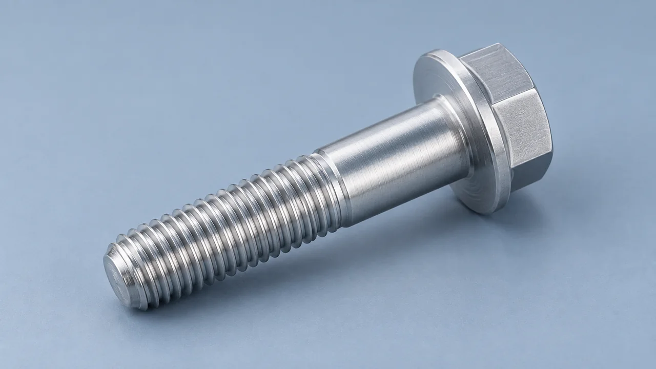
A hex flange bolt combines the wrenching head and a circular flange in one piece. That larger outline can spread the load, but it does not establish that the head will seat correctly on a particular component. The hole entrance, the underhead transition and the available bearing surface need to work together.
For a drawing review or an RFQ, thread size and length are only part of the specification. Check where contact is intended, what may obstruct it and whether the proposed washer, finish and tightening conditions match the joint design.
Separate the outside profile from the bearing surface
On the product drawing, d identifies the nominal thread diameter and s the width across the hexagon flats. The flange outside diameter, dc, and the bearing-face diameter, dw, describe different features. Read each symbol together with its maximum or minimum limit; the widest outline is not necessarily the full flat bearing diameter. [1]
Dimension symbols · expand or collapse
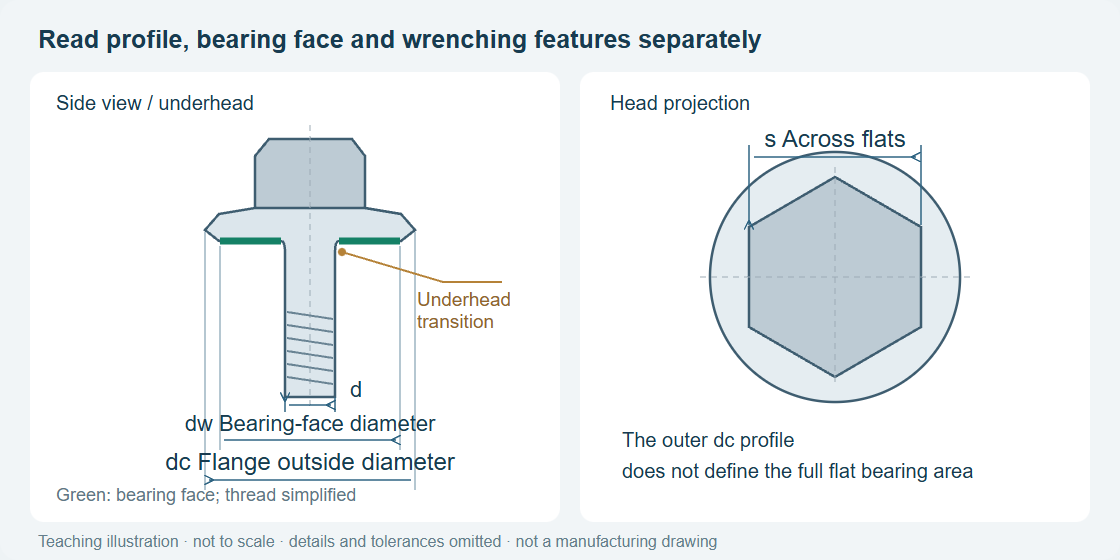
The standard designation matters as well. The public title of ISO 4162:2012 distinguishes product grade A from wrenching features to product grade B. These product grades concern a different specification from mechanical property classes such as 8.8 or 10.9. A similar head shape and the same thread size do not establish interchangeability. [2]
Give the underhead fillet room to clear the hole
Check three things together: whether the shank passes through the hole, whether the hole entrance clears the underhead transition and whether the intended bearing face reaches the component's plane. If the hole edge meets the fillet first, reaching the tool's torque setting alone does not confirm correct seating.
Underhead geometry and the mating component
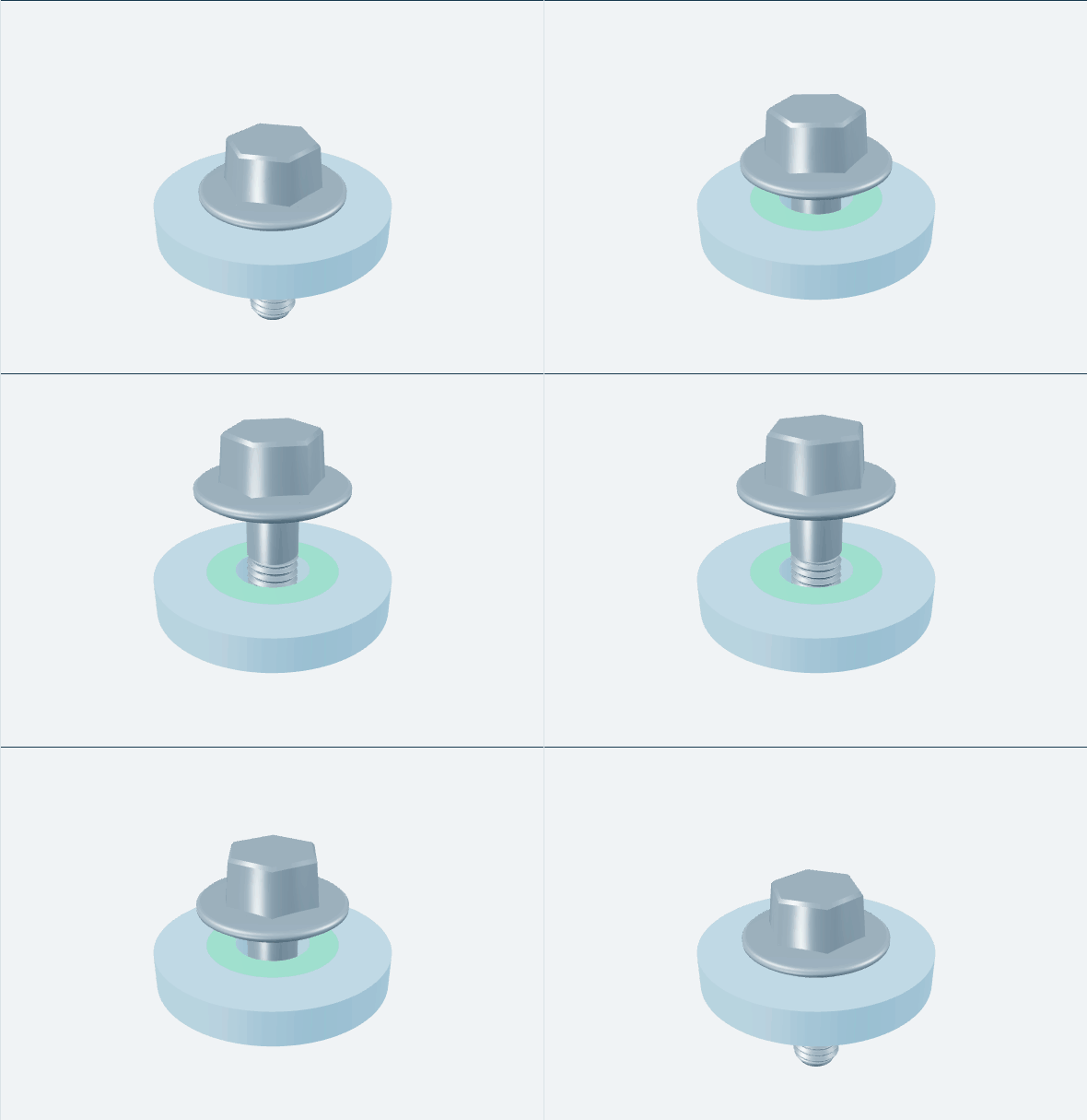
Green: intended bearing region
Watch the flange underside, head-to-shank transition and hole entrance. Separation reveals the geometry; it is not a tightening sequence.
At the underhead detail, which feature touches first—and can the flat bearing face seat?
The hole entrance clears the fillet
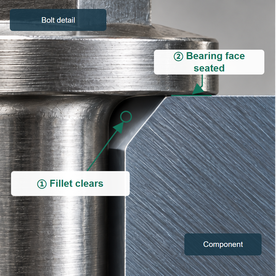
At ①, relief surrounds the fillet. At ②, the flange bearing face meets the component plane.
The hole edge meets the fillet first
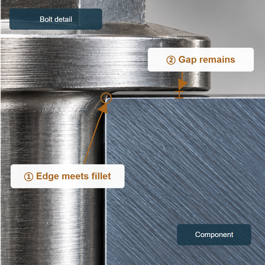
At ①, the edge stops against the fillet. At ②, the outer bearing face still sits above the component.
A shank that passes through the hole does not establish fillet clearance or flat bearing contact.
A chamfer must therefore be reviewed against the actual underhead contour. Too little relief can cause interference; a larger chamfer also enlarges the opening at the surface. Confirm hole size, chamfer and positional tolerances from the joint drawing and applicable standard rather than adopting a universal clearance rule.
A larger opening leaves less bearing footprint
For an ideal concentric joint with full planar contact, the footprint can be pictured as an annulus. Hold its outer boundary fixed and enlarge the opening: the remaining projected area becomes smaller. Dividing load by area gives an average pressure, not the actual local pressure distribution.
Keep the outer bearing boundary fixed and compare the area left as the opening grows.
Smaller opening
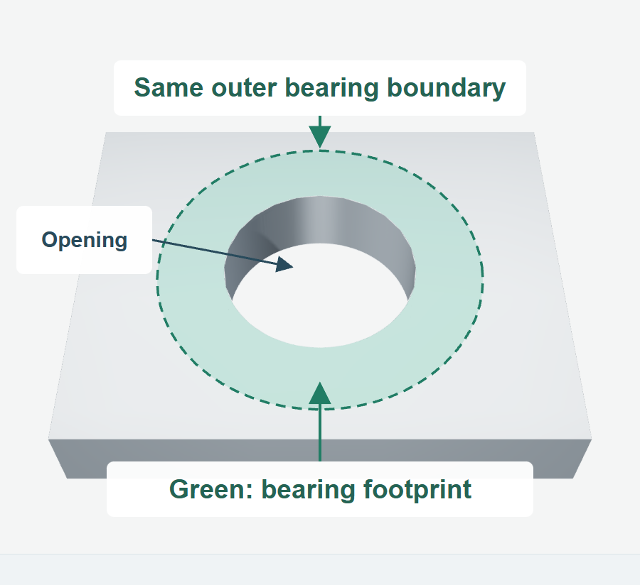
The dashed outline fixes the outer boundary; the smaller opening leaves a wider green annulus.
Larger opening
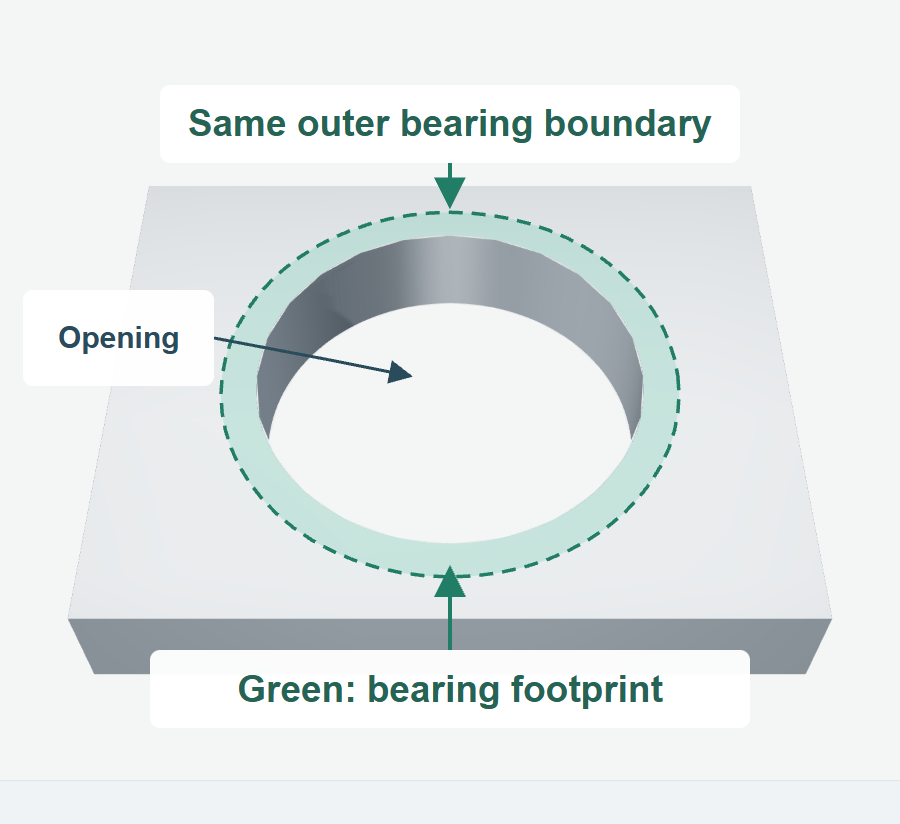
The outer boundary is unchanged; the larger opening leaves a narrower green annulus.
Bossard's assembly guidance identifies material, manufacturing condition, surface treatment and temperature among the factors affecting underhead surface pressure. A broad flange can distribute load, but it does not by itself prevent indentation in thin, soft or coated parts, nor justify a higher allowable preload. [3]
Inspect the features that control seating
Bolt production may use cold forming, hot forging or machining; external threads may be rolled or cut. The route and sequence depend on material, dimensions, shape and technical requirements. A manufacturer's published flange-bolt example describes that particular process, not a mandatory route for every bolt or evidence of Wohe's production capability. [4]
For seating, inspect the finished flange profile, bearing-face form and condition, underhead transition, shank and thread, including burrs or raised material that may obstruct contact. Dimensional, geometrical, surface-defect and mechanical requirements each need their own applicable acceptance criteria. Measuring the flange diameter or completing a trial assembly does not replace those checks.
A trimmed edge establishes an outline; it does not prove correct bearing contact. Likewise, a thread that screws in successfully says nothing conclusive about underhead pressure or the preload in the complete joint. Link each inspection location to the function it must perform.
Review washers and tightening conditions as a system
Whether a washer is needed depends on the component surface, hole form and locking arrangement. A flange may have a plain or serrated bearing face; the name alone promises no universal resistance to loosening. Assess each configuration under its specified conditions.
For its own wedge-locking washers, Nord-Lock gives pairing guidance involving flanged fasteners and larger-outside-diameter washers for large or slotted holes and soft bearing surfaces. That product-specific guidance is not a rule to fit, or omit, a washer under every flange bolt. [5]
Thread friction and underhead friction influence the torque–preload relationship. Changing a washer, coating or lubricant calls for a review of that relationship; a generic torque table should not be carried over when those conditions are unknown. [6] [7]
For a Wohe Fastener enquiry, send the bolt standard and size together with the hole and chamfer drawing, component material and thickness, finish, washer arrangement and assembly requirements. The bolt product range provides product context; the complete joint drawing is needed to confirm the fit and tightening basis.
Technical references
- YJT: GB 5787—1986 product dimensions (Chinese). Use the specified standard itself for technical requirements.
- ISO 4162:2012: public catalogue title and abstract.
- Bossard: Surface pressure when mounted, January 2025, pp. 53–55.
- Wilson-Garner: How a Bolt Is Made. General routes and a particular hex flange bolt example.
- Nord-Lock: Original Washers User Guide.
- Bossard: Friction and Friction Coefficients.
- Nord-Lock: Why does torque vary when tightening and untightening?