Two set screws with the same thread size and length can make very different contact with a shaft or mating part. A flat point bears on a face, a cup point presents an outer rim, a cone point tapers towards its end, and a dog point projects into a locating feature. The point needs to be selected together with the surface it contacts.
Set screws are also commonly called grub screws. An RFQ that gives only the thread size and length leaves the working end undefined. Confirm the mating geometry, permitted marking and need for repeated adjustment before finalizing the material, hardness and assembly requirements.
Read the drive socket and the point separately
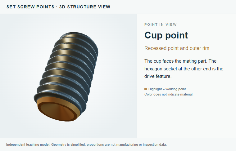
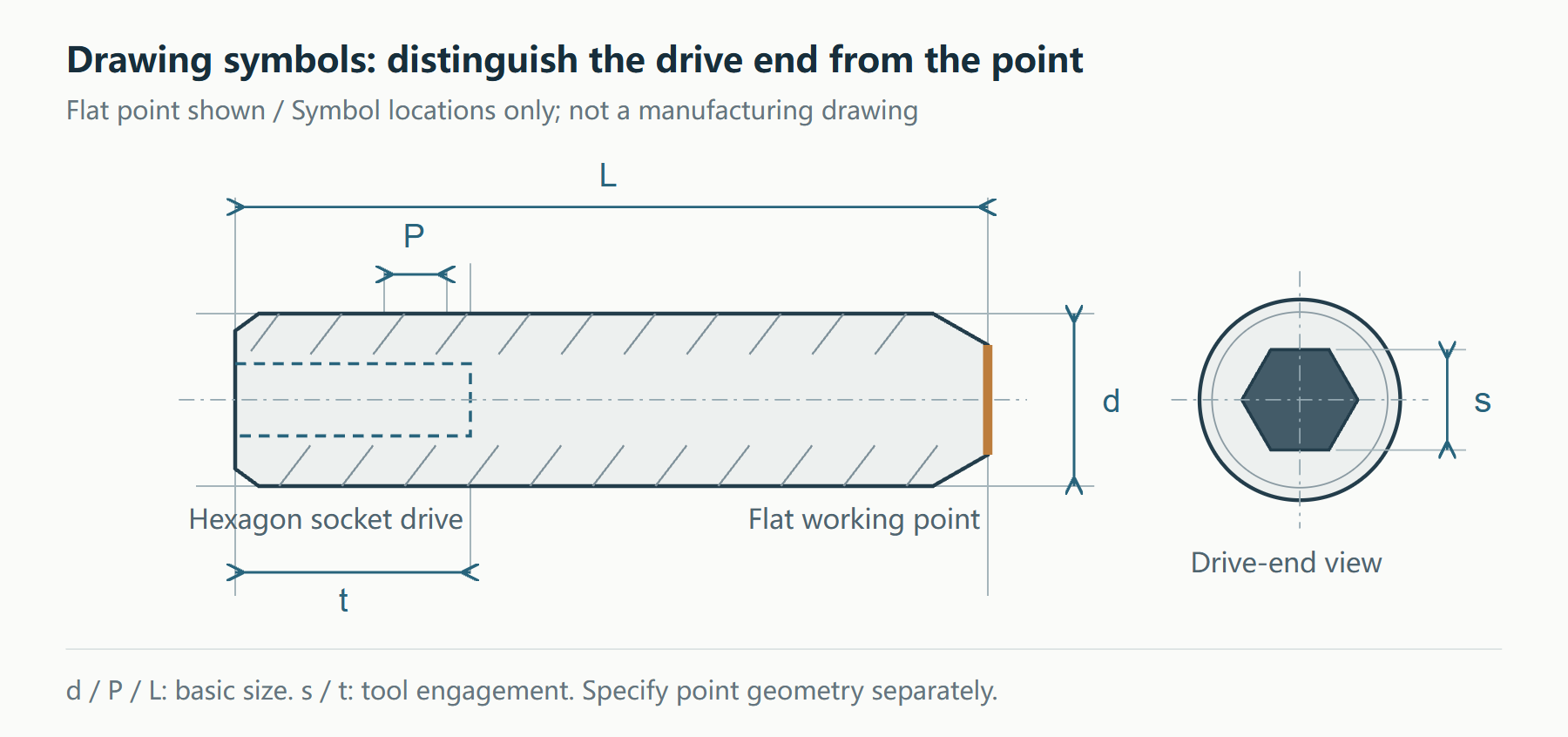
On a hexagon socket set screw, the internal hexagon engages the tool and transmits tightening torque. The flat, cup, cone or dog point is at the opposite end and contacts the mating part. The recess in a cup point is a working-end feature; it is separate from the drive socket.
Open the larger drawing
Scroll sideways within the drawing to read the full width.
d, P and L describe the basic size. s and t help define tool engagement. Depending on the point type, the drawing may also specify a point diameter, angle, end flat or projection. A front-facing product photograph rarely resolves all of these features.
What changes across four point types
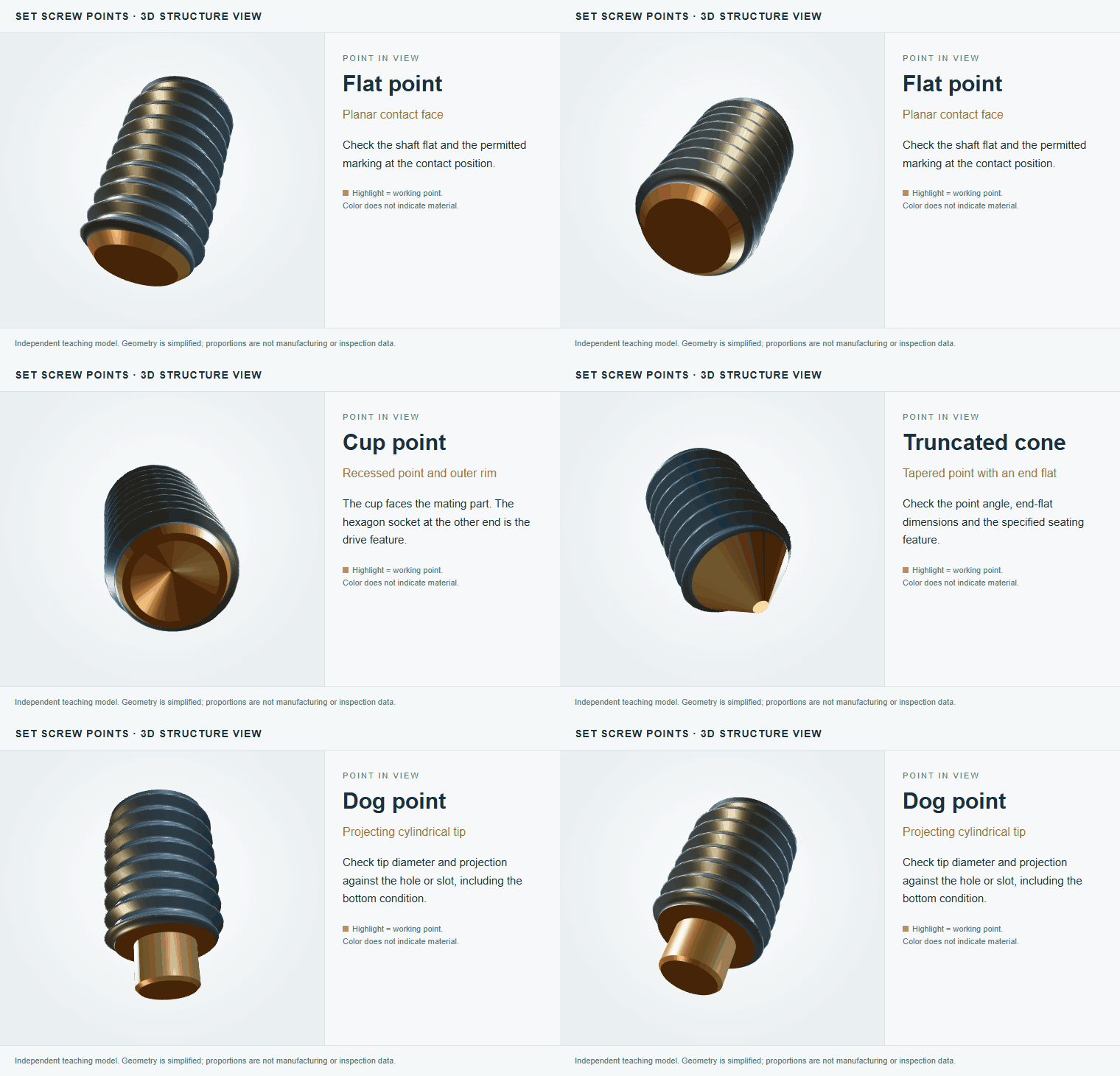
The rotating illustration shows flat, cup, truncated cone and dog points in sequence. A warm highlight identifies the working point so that the contact face, cup recess, taper and cylindrical projection can be compared. [2]
Rotating model
| Point | Contact feature | What to confirm |
|---|---|---|
| Flat | A planar end face bears against the mating part. | Whether a flat is provided; adjustment frequency; the permitted surface marking. |
| Cup | The rim around the point recess contacts the surface. | Whether indentation is acceptable and how point and shaft hardness interact. |
| Truncated cone | A tapered end provides localized contact or location. | The intended seat or recess, permitted indentation, point angle and end-flat dimensions. |
| Dog | A cylindrical tip enters a prepared hole or slot. | Tip diameter, projection, hole or slot size and position, and the bottom condition. |
Point selection also depends on material, surface condition, loading and assembly verification. [3]
Manufacturing features to check at inspection
Set-screw production can involve cold forming, turning and other operations. The route depends on material, size, quantity and tolerance requirements. Similar-looking points can be made by different routes, so inspection needs to address the drive socket, external thread and working point separately. [6]
Drive socket: check effective tool engagement. Sockets may be formed or broached, depending on the process. Across-flats size s, depth t and the socket mouth must meet the specified requirements. Check that the tool can enter sufficiently and that burrs or damage do not obstruct it. A similar-looking opening does not establish an equivalent torque-transmitting engagement. [6]
External thread: inspect the resulting fit and condition. Rolling forms the thread through plastic deformation; cutting removes material to produce the profile. The finished thread still needs to satisfy the drawing's tolerance and inspection requirements. Where the point receives secondary machining, adjacent thread burrs and damage deserve attention. If GO/NO-GO gauging is required, use gauges and acceptance rules appropriate to the specified thread. [6]
Working point: inspect the geometry that actually contacts the part. For a flat point, check the end face and its specified relationship to the axis. For a cup point, check the recess and rim. For a truncated cone point, check the angle and end flat. For a dog point, check tip diameter, projection and any specified concentricity requirement. Judge chipped edges and residual burrs against the drawing and intended mating condition. Dimensional measurement and visual inspection provide complementary information.
Match the point to the shaft or locating feature
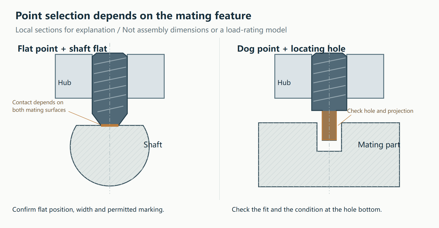
A flat point on a round shaft does not automatically contact across its whole face. If the design relies on a prepared shaft flat, confirm its width and position against the point. NBK's coupling installation guidance likewise shows the flat on a D-shaped shaft aligned with the set-screw fastening position. [4]
Open the larger mating-section drawing
Scroll sideways within the drawing to read the full width.
Where holding action depends on the point rim indenting the shaft, shaft hardness affects the contact mechanism. A hard surface that resists indentation differs from a softer surface into which the point embeds. Holding behavior established under one condition should not be transferred to the other without verification. Raised material or burrs at an indentation can also hinder removal, repositioning and repeated adjustment. [5]
Material condition belongs in the same review. For steel set screws requiring heat treatment, confirm hardness and relevant surface-quality requirements, including decarburization where applicable. Austenitic stainless grades such as 304 and 316 depend on material condition and cold work; the quench-hardening approach used for suitable alloy steels cannot simply be applied to them. Specify material and the applicable hardness class or other mechanical requirements when quoting and accepting the part. [7]
A flat point therefore does not guarantee an unmarked surface, and a cup point alone does not establish suitability for every vibration condition. Review surface protection, adjustment frequency, material and hardness, tightening conditions and service loads together. Where surface marking is tightly limited, assess a contact arrangement designed to protect that surface.
Define the point and mating conditions in the RFQ
A usable set-screw specification connects the screw to its mating part. Alongside quantity, include:
- Form and size: drive type, point type, thread size and pitch, nominal length, and the standard number and edition.
- Material and performance: material, applicable hardness class or mechanical requirements, and finish. A general description such as “high strength” leaves important requirements unresolved.
- Mating-part details: a round surface, flat, recess or locating hole, with the relevant dimensions, hardness and surface requirements.
- Use and acceptance: repeated adjustment needs, permitted marking, and how tightening, holding performance and resistance to loosening will be verified.
These set screws have a different function from bolts used in tensile joints. Confirm their mechanical requirements under the relevant set-screw specification rather than inferring them from an ordinary bolt property-class marking. [2]
The ISO catalogue checked on 23 October 2026 lists 2026 editions of ISO 4026, ISO 4027, ISO 4028 and ISO 4029 for flat, truncated cone, dog and cup points respectively. Existing drawings and orders still need to be checked for their specified edition. Resolve differences between standards or editions before approving a substitution. [2]
When requesting a quote from Wohe Fastener, send the screw drawing and mating-part drawing together, with the intended contact position marked for review.
Technical references and illustration notes
- Drawing-symbol locations and product structure: YJT flat-point product data and cup-point product data (Chinese).
- ISO public catalogue: ISO 4026:2026 (flat), ISO 4027:2026 (truncated cone), ISO 4028:2026 (dog) and ISO 4029:2026 (cup).
- Point applications: Unbrako engineering guide and Accu grub-screw guide. Manufacturer guidance explains contact conditions; applicability must be confirmed for the selected product.
- Shaft-flat alignment: NBK coupling installation guidance.
- Shaft hardness, indentation and adjustment: Ruland shaft-collar guidance.
- Manufacturing routes and drive engagement: Ruland socket set screws, the set-screw sections of the Unbrako engineering guide, and Bossard forming and machining information. Inspection suggestions connect geometry to the mating task; they are not reproduced standard clauses.
- Material condition: the set-screw heat-treatment discussion in the Unbrako guide, Outokumpu mechanical-property guidance and austenitic stainless information.
The two drawings and four models were independently created for explanation, with product structure informed by YJT/partsCAD reference pages. Use the agreed standards and drawings for actual dimensions, tolerances, materials and acceptance requirements.